HiRISE DTMs are made from two images of the same area on the ground, taken from different look angles. All the stereo pairs acquired so far
are available
here. Not all of these have been made into
DTMs due to the time-intensive process. Creating a DTM is complicated and involves sophisticated software and a lot of time, both computing
time and human operator time.
The great advantage of a HiRISE DTM is the high resolution of the source images. As a general guide, terrain can be derived at a post
spacing about 4 time the pixel scale of the input images. HiRISE images are usually 0.25 - 0.5 m/pixel, so the post spacing is 1-2 m
with vertical precision in the tens of centimeters.
The basic steps of creating a DTM are:
- Prepare the images for ingestion into the stereo software
- Triangulate the images
- Generate the DTM
- Edit DTM if necessary
- Orthorectify images
In order to prepare the images, we must first correct the geometry by removing any optical distortions inherent to HiRISE. Then the spacecraft
pointing information at the time of each observation is gathered.
Triangulation, also called bundle adjustment, requires the most operator skill and time. The purpose of triangulation is to register the stereo
images to each other and to the MOLA elevations. The end result is tied to the global elevation map produced by the MOLA instrument team. This is
the same map that you see in the context map pane of every HiRISE observation page.
Once the images are triangulated, then the terrain model can be generated. This step is computationally intensive, but automated, so it just takes a lot of
computer time.
The output of terrain extraction is reviewed for any artifacts or errors. These are edited out if possible. Since editing is extremely
time-consuming, it is usually done on easily corrected errors and in the areas of most interest to the researcher. The less editing we have to do, the
better, so a lot of effort goes into preparing the images so that the input is as high quality as possible. The excellent contrast and value
range of HiRISE imagery usually result in high quality terrain extraction that requires minimal editing.
After we have a terrain model, we can make other products, such as orthoimages. An orthoimage is a picture that has been orthorectified. This means
that the pixels have been projected so that at each pixel it is as if you are looking directly down at the terrain. In the original stereo images,
we rely on the fact that there are topographical distortions (parallax) to derive the elevations in the terrain model. In the orthoimages,
all topographic distortions have been removed. Orthoimages are made of the source stereo pair for a DTM. If other images exist that cover the DTM, we can also orthorectify them.
The final products are map projected using the same mapping definitions as the regular HiRISE RDR products.
For a detailed explanation of the process used to create HiRISE DTMs, see
Kirk, R. L.,
et al. (2008).
Researchers use DTMs to take measurements and model geological processes. DTMs are very powerful research tools. There is a long waiting list for these
products because they are so valuable and so difficult to produce. HiRISE DTMs and orthoimages are released to the Planetary Data System (PDS) as
they become available.
Standard PDS products are usually quite large files. The links provided on the DTM project page will download the files to your system. To get a quick
view of the DTM or orthoimages, click on the Extras links to see a reduced version of the products, displayed as images, grayscale, shaded relief and
colorized elevation maps.
Standard PDS products:
- The DTM in standard PDS image object (.IMG) format with an embedded label
- Orthoimages at the same resolution as the DTM, in JPEG2000 format with detached label
- Orthoimages at the resolution of the original image, in JPEG2000 format with detached label
Extras available in the PDS Extras directory (letters in parentheses correspond to PDS file names such as .br.jpg):
- Browse (br), annotated browse (ab), and thumbnail (th) jpegs of the DTM as a grayscale image
- Browse (sb), annotated browse (sa), and thumbnail (st) jpegs of the DTM as a shaded relief image
- Browse (cb), annotated browse (ca), and thumbnail (ct) jpegs of the DTM as colorized altimetry
- Browse (br), annotated browse (ab), and thumbnail (th) jpegs of the lower resolution orthoimages
PDS product naming convention for HiRISE DTMs:
PRODUCT_ID = aabcd_xxxxxx_xxxx_yyyyyy_yyyy_Vnn
where
aa = DT, indicating it's a DTM product
b = type of data
E = areoid elevations
c = projection (others are possible but these are the important ones)
E = Equirectangular
P = Polar Stereographic
d = grid spacing (think of this as pixel scale in meters)
A = 0.25 m
B = 0.5 m
C = 1.0 m
D=2.0 m
xxxxxx_xxxx = orbit number and latitude bin from SOURCE_PRODUCT_ID[1]
yyyyyy_yyyy = orbit number and latitude bin from SOURCE_PRODUCT_ID[2]
V = letter indicating producing institution
- U = USGS
- A = University of Arizona
- C = CalTech
- N = NASA Ames
- J = JPL
- O = Ohio State
- P = Planetary Science Institute
- Z = other
nn= 2 digit version number
PDS product naming convention for HiRISE Orthoimages:
ORTHOIMAGE PRODUCT_ID = XSP_xxxxxx_xxxx_CCC_S_NN_ORTHO where
XSP_xxxxxx_xxxx = HiRISE source observation ID
(mission phase_orbit number_target code)
CCC = color content
- RED = visible RED, 1 band image
- IRB = 3 band enhanced color (IR, RED, BG)
S = grid spacing (comparable to the DTM naming convention above)
- A = 0.25 m
- B = 0.5 m
- C = 1.0 m
- D = 2.0 m
NN = a sequence number to distinguish between orthorectified
images from the same HiRISE observation that may be created from different DTMs.
ORTHO indicates that the image has been orthorectified
Known Artifacts:
These are known artifacts present in some, but not all, HiRISE DTMs. They may not be present in this DTM! Look at the terrain shaded
relief to detect these before using the DTM!
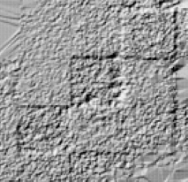
“Boxes”
- Some DTMs have square areas that are usually about .5-1 m different in elevation from the surrounding areas. These are
artifacts of the processing algorithms used in Socet Set ((c) BAE Systems). There may be goups of these boxes. These
artifacts are usually left unedited, so the user should look for such artifacts in a terrain shaded relief map before
using those parts of a DTM for analysis.
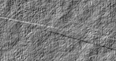
CCD seams
- A HiRISE image is made up of 10 individual images, stitched together along their long edges. In a DTM, these seams can be
visible as long lines. These seams are difficult to remove, and so are usually left unedited.
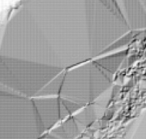
Faceted areas
-
Areas that were very bland (low contrast) or deeply shadowed with low contrast and low signal may have a "faceted" look to them.
Terrain in these areas may only generally approximate the shape of terrain.
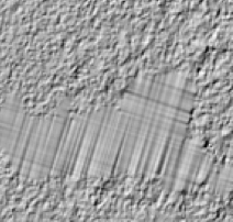
Manually Interpolated areas
- Some manual editing tools result in a geometric pattern due to interpolation from boundary posts. The user should be aware of
these and compare the DTM to the images to understand the quality of the interpolation.